Battery Backup, AC OK and Battery Low Alarm Functions
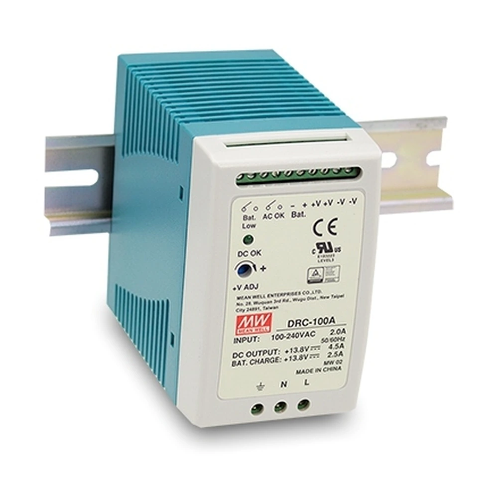
The MEAN WELL DRC-100 Series integrates DC power supply, battery charging and backup control in a DIN rail design. It is intended for security systems, access control, alarm systems, emergency lighting, central monitoring systems and other applications that require continued DC power when AC mains power is interrupted.
When AC mains is available, the DRC-100 Series supplies power to the connected load while charging the external battery. If AC input fails, the battery automatically supplies the load through the internal backup control circuit, allowing critical equipment to continue operating without a separate external DC UPS module.
Both DRC-100A and DRC-100B also provide AC OK and Battery Low alarm outputs for integration with controllers, alarm panels and monitoring systems. These alarm functions are provided through relay contact outputs with a maximum rating of 30V / 1A.
Battery Backup Operation
The DRC-100 Series is designed for direct integration with an external battery. During normal AC operation, the power supply provides energy to the load while charging the connected battery at the same time.
When AC mains power is interrupted, the battery automatically begins supplying power to the connected load. This allows the DRC-100 Series to function as a DIN rail power supply with battery backup for systems that must remain operational during temporary AC power failure.
The DRC-100A is intended for 12V battery architectures, while the DRC-100B is intended for 24V battery architectures.
AC OK Alarm Signal
The AC OK signal allows an external monitoring circuit to detect whether the power supply is operating normally from AC mains.
According to the DRC-100 alarm logic, the AC OK relay contact is ON when AC power is normal and OFF when AC input fails. In the suggested application table, the monitored signal is described as Low when the power supply is ON and High or open when the power supply turns OFF.
This signal can be connected to an alarm panel, PLC input, controller or monitoring circuit to provide AC power status feedback.
Battery Low Alarm Signal
The Battery Low signal provides early warning when the connected battery voltage falls below the specified threshold.
For DRC-100A, the Battery Low signal is activated when battery voltage falls below 11V. For DRC-100B, the threshold is below 22V.
The alarm output changes state according to battery condition, allowing security systems, monitoring controllers or alarm equipment to detect low battery voltage before battery cut-off occurs.
Battery Low Cut-Off Protection
To help prevent excessive battery discharge during extended backup operation, the DRC-100 Series includes battery low cut-off protection.
The specified battery cut-off voltage is 10 ±0.5V for DRC-100A and 20 ±1V for DRC-100B.
This function works together with the Battery Low alarm signal to provide both early warning and low-voltage battery protection during backup operation.
Relay Contact Alarm Output
The DRC-100 Series provides AC OK and Battery Low signals through relay contact outputs.
An external voltage source is required for the alarm circuit. The datasheet specifies a maximum applied voltage of 30V and a maximum current of 1A.
This relay-based signaling allows the DRC-100 Series to interface with alarm panels, controllers and monitoring equipment that require external power status and battery condition feedback.
Terminal Assignment and System Connection
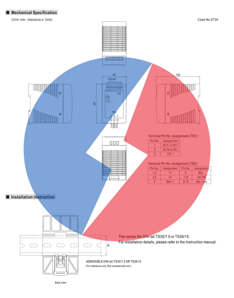
The DRC-100 Series provides dedicated terminals for AC input, DC output, battery connection and alarm signaling.
The output-side terminal block includes connections for:
- +V / -V for the main DC load output
- Bat. + / Bat. – for the external backup battery
- AC OK for AC power status monitoring
- Bat. Low for low battery status monitoring
For correct installation, battery wiring and alarm circuit design, engineers should follow the terminal assignment and suggested application diagram provided in the DRC-100 datasheet.
DIN Rail Installation
The DRC-100 Series is designed for installation on TS35/7.5 or TS35/15 DIN rail. Its 55 × 90 × 100 mm enclosure allows integration into security panels, control cabinets, access control enclosures and other space-constrained electrical installations.
The datasheet recommends installation clearances of 40mm above, 20mm below and 5mm on the left and right sides when operating continuously at full power. When an adjacent device is a heat source, a 15mm side clearance is recommended.
Need wiring and installation details for the DRC-100 Series? Review the connection diagram, terminal assignment and mechanical drawing below, or refer to the official DRC-100 datasheet for complete battery wiring, alarm output and DIN rail installation information.